Romtec Utilities installs new pump and lift stations for many different applications and water types. A frequent scenario when designing a new pumping system is joining the pump station into an existing force main, that is piping that is pressurized. From a practical point of view, this is a terrific approach. It utilizes existing infrastructure and materials and simplifies the installation process of a new pump station. When tying into an existing force main, the pump station must be designed correctly to ensure a fully functional pumping system.
From an engineering perspective, tying into an existing force main means overcoming pressure. A force main, by definition, is a pressurized pipe either by pumps or compressors, typically pumps. In order to understand the issues associated with tying into an existing force main, three project cases will be viewed where this type of work was completed. Each project faces a slightly different scenario that needed to be addressed in the pump station design. Romtec Utilities provided the specific expertise necessary to design, engineer, and supply complete pump stations that tied into existing force mains.
Praxair Hydrogen Refinery – Port Arthur, Texas –
Pumping at Sustained High Pressure
Praxair added a hydrogen plant to an existing Valero petrochemical facility as part of an expansion to manufacture ultra-low-sulfur diesel. The new hydrogen plant included a Romtec Utilities industrial process water pump station. The existing Valero facility offered Praxair on-site treatment for its process water. The caveat was that the existing force main could have up to 100 psi of pressure. In this scenario, the pump station needed to overcome the existing psi of the force main in order to pump process water to treatment.
Overcoming 100 psi requires a high pressure pump with a unique pump curve. For this project, the flow requirements for the expected inflow, storage capacity, and necessary pumping rate made utilizing a submersible pump impossible. There simply were no submersible pumps capable of meeting the required curve. Romtec Utilities, instead, redesigned its system to utilize surface-mounted, self-priming pumps. Using these pumps meant that Romtec Utilities could supply a typical pump station with reliable and affordable components. It also meant that the pump station could overcome the 100 psi of force main pressure to pump into the existing water treatment system.

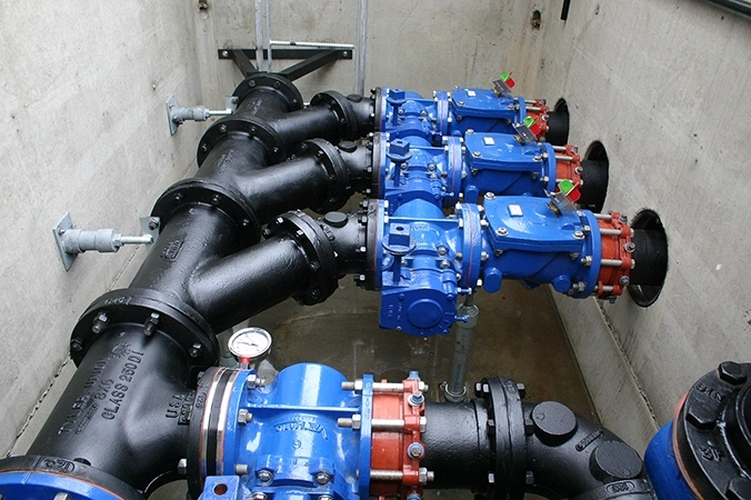
In this scenario, using high pressure pumps solved the problem of pumping into the existing force main at 100 psi. The challenge was that these high pressure pumps must always pump against high pressure. If the existing force main pressure dropped for any reason, like opening a downstream valve, the pumps would not pump correctly without adequate pressure. To ensure consistent high pressure pumping conditions, Romtec Utilities included a back-pressure sustaining valve in the design of this pump station.
The back-pressure sustaining valve monitors the differential pressure between the force main and the pump station discharge piping. If the force main pressure drops, the valve reduces its opening to increase pressure for the pumps to pump against. This keeps the high pressure pumps working within their specified pumping conditions from the pump curve while still meeting the lower pressure conditions of the force main. When the force main is at the maximum 100 psi, the back-pressure sustaining valves open fully and the pumps meet the pressure directly.
Using the back-pressure sustaining valve in this application made sense because the chosen pumps were designed specifically for high pressure pumping and the water was free from solids. The valve keeps the pumps operating within their specified curve and without solids in the water, the reduction of the valve aperture does not pose a risk of clogging. In wastewater applications where suspended solids are probable, a back-pressure sustaining valve is not the best approach.
Benham Ridge Homes – Sammamish, Washington –
Using Pressure Sensing for Variable Head Requirements
Pacific Properties, a land developer in Washington, was adding a new development phase to a residential neighborhood. The existing homes were tied to an existing wastewater lift station and corresponding force main. The developer chose to tie its new lift station into the existing force main to treatment. Like in the previous scenario, the existing force main had high pressure conditions. In this scenario however, wastewater with a good probability of suspended solids ruled out the use of a back-pressure sustaining valve due to the risk of clogging.
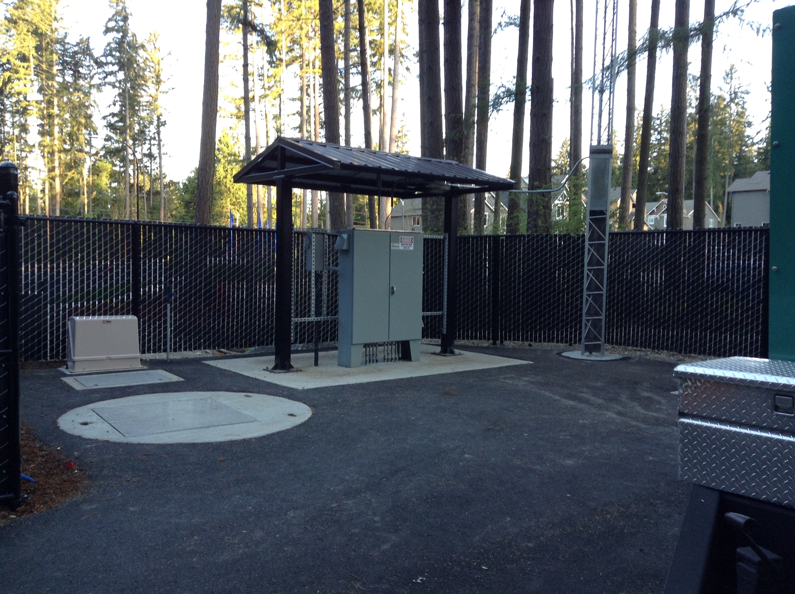
To eliminate this concern, Romtec Utilities chose a different approach to pumping into the existing force main while meeting the varying pressure conditions. This approach involved using a pressure transducer and variable frequency drives (VFDs) to control the pump speed relative to the force main pressure. In this configuration, the pressure transducer is located on the discharge piping before the junction to the existing force main, and the VFDs are located in the control panel of the lift station.

When a pump cycle starts, pressure in the discharge piping increases. The pressure transducer measures the increase in pressure and relays that information to the control panel. At the control panel, the pressure reading is relayed to the VFDs as an analog signal. The VFDs, in turn, increase the electrical frequency to the pump motors causing the impeller RPMs to increase. As the pumps speed up, the pressure in the discharge piping increases until it is higher than the pressure in the existing force main, allowing the lift station to pump into the force main. Once the pressure stabilizes, the VFDs supply an analog electrical frequency and the pumping rate becomes constant.
This process works by monitoring pressure in the force main just like with the Praxair project. Instead of a valve closing and opening to control the back-pressure, the pump motors go faster and slower to meet the force main pressure. This design is much more suited to a wastewater application because it does not restrict the flow, increasing the probability of clogging. VFDs can also be used when monitoring the flow rate as opposed to the force main pressure.
Camphora Apartments – Soledad, California –
Pumping with Variable Frequency Drives
A land developer in Soledad, California wanted to construct a new apartment complex just outside of town. In order to reduce construction costs, the developer chose to integrate the new sewer line into an existing force main from the Salinas Valley State Prison. The prison used two pump stations to handle its sewage, and the pumping rates varied day to day, ranging over 400 gpm. In this scenario, the developer wanted the pump station to pump at the same flow rate regardless of the pressure in the existing force main. Again, since this was a wastewater application, Romtec Utilities chose not to use a valve to avoid clogging concerns.
In order to achieve a consistent pumping rate, the easiest solution was to use a flow meter in the discharge piping. The flow meter was engineered much like the pressure meter in the previous project. It was located on the discharge piping prior to the force main junction. The VFDs were, again, located in the control panel and used to relay information from the flow meter to the pumps. This particular system also included a pressure transducer to serve as a redundant control device in case the flow meter not functioning.

For this pumping system, the target pumping rate (flow) is 160 gpm. When the pump cycle starts, the flow in the discharge piping is measured by the meter. A signal is sent to the control panel when the pumping rate is below the target of 160 gpm. In turn, the VFDs increase the electrical frequency to the pump motors, and the pumps increase their RPMs. As the RPMs increase, the pumping rate increases until the flow meter detects that the lift station is pumping at the target rate of 160 gpm. Once the target pumping rate is achieved, the VFDs send a constant frequency and the pumps operate at a constant speed.
In this lift station, if the pressure in the force main changes, it causes the flow rate to either increase or decrease. The meter relays to the VFDs. The VFDs change the electrical frequency. The pumps operate accordingly until the target pumping rate is met. For an application where a specific pumping rate is preferred, using a flow meter with VFDs to control the pumping rate is a very effective system. Adding in the pressure transducer provides a failsafe for the system should the flow meter stop working or experience any errors.

Comments 3
Hello.
I need technical support about force main sewer system.
A building sewer invert is lower than main sewer connection.
Please give us best answer for this issue.
Thank you.
Author
Jason, thank you for your comment. Romtec Utilities will be in touch with you!
use a pump.